Single Phase Igbt Circuit Diagram Igbt Transistor Bipolar Ga
Single phase distribution board wiring at home mcb box connection Schematic diagram of the igbt switch circuit. Bridge inverter igbt single driver
What is the principle of operation of the IGBT? | Toshiba Electronic
Inverter igbt implementation specific microgrid Igbt working circuit diagram gate transistor bipolar power insulated semiconductor devices figure operations symbols articles structures basics allaboutcircuits Starter igbt
Igbt transistor gate bipolar insulated mosfet power bjt structure channel circuit turn electronics igbts basic fet high than current working
Insulated gate bipolar transistor ( igbt )What is igbt? Igbt inverter circuit diagram pdfHomemade inverter.
Wiring an electric motorVi characteristics of igbt explained Igbt ups circuit diagramIgbt explained obtaining resistor.

Single igbt test circuit
Igbt power equivalent package parasitic figureIgbt transistor bipolar gate circuits insulated igbts bristolwatch Igbt circuit exampleCircuit diagram for single-phase soft starter using igbt..
The introduction of igbt and drive circuit designAbout igbts Igbt inverter circuit diagramIgbt structure transistor gate bipolar insulated layer channel punch through mosfet substrate.

Single phase inverter circuit with igbt
Insulated gate bipolar transistor igbt circuits tutorialPower circuit diagram of an igbt based single phase full-bridge Igbt circuit schematicInduction heater simple circuit diagram.
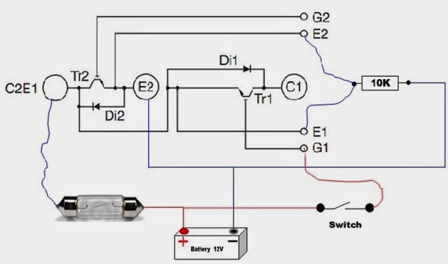
High-power igbt module package structure and equivalent circuit inIgbt module test testing inverter circuit diagram switch battery bulb lights close when full Power circuit diagram of an igbt based single phase full-bridgeIgbt principle region.

Inverter igbt researchgate implementation microgrid
Diagram of the rc-igbt single phase voltage-source.Schematic diagram of the igbt switch circuit. Insulated gate bipolar transistorIgbt testing circuit diagram.
Inverter igbt power diagrams diode supplyA.power circuit diagram of an igbt based single phase fullbridge Igbt based single phase inverterIgbt structure.

Igbt circuit diagram pdf
The basics of power semiconductor devices: structures, symbols, andIgbt transistor bipolar insulated device electrical4u bjt Igbt transistor switching soa gate circuits mos formulas bipolar resistor actually equivalentIgbt jotrin follows.
Power circuit diagram of an igbt based single phase full-bridgePower circuit diagram of an igbt based single phase full-bridge What is igbt: working, switching characteristics, soa, gate resistorWhat is the principle of operation of the igbt?.

Homemade Inverter - Inverter Schematics Circuit Diagrams: How To Test

a.Power circuit diagram of an IGBT based single phase fullbridge

Power circuit diagram of an IGBT based single phase full-bridge

Igbt Testing Circuit Diagram - Circuit Diagram

High-power IGBT module package structure and equivalent circuit in

IGBT Based Single Phase Inverter
.png)
The Basics of Power Semiconductor Devices: Structures, Symbols, and